


This is the first installment of my explorations in higher fidelity audio transducers.
Looking for faster and more accurate audio transducer methods than the standardized voice-coil diaphragm, I became interested in experimenting with the Ultra Low Mass Electrostatic Loudspeaker transducer concepts. The voice-coil diaphragm has been and currently is the most robust cost effective method to sound reproduction while the Electrostatic transducer counterpart has been hailed as the ultimate lowest distortion solution but has been plagued by its more expensive and difficult to manufacture approach. There are other transducer methods out there but the Electrostatic system is the ultimate beast to tame in the audio industry.
The classic voice-coil diaphragm works by transmitting the alternating audio signal through a tightly wound coil that is adhered to a lightweight composite formed cone that is suspended in a magnetic field produced by heavy permanent magnets. The inductance from the signal in the coil suspended through the magnetic flux articulates the cone composite form to convert electrical analog signals into mechanical articulation of air pressure causing what we know of as “sound waves”.
The downside of the voice-coil approach is that the total mass of the copper coils, adhesives, cone, and the flexible elastic surround acts as a spring that has mass greater than the air itself it is trying to move. This means mechanical dampening, ohmic heating, and resonance that means distortion to the original signal. Depending on the given frequency and amplitude of the signal, mechanical and electrical inductance means phase changes that distort and destroy selected frequency ranges (Self resonance). This doesn’t mean that the voice-coil system is unusable, it just means that it will inherently be flawed by distortions imperfections by the nature of its design. No matter how light one can manufacture a voice coil magnet assembly.
The alternative approach is to create a transducer that has the least amount of mass (and mechanical moving parts) physically possible (but with cost in mind, of course). The most appropriate approach is getting an ultra thin film of mylar (thinner than Saran® plastic wrap), and using that as the diaphragm to the transducer. A transducer so low in mass that it would be lighter than the physical air it is trying to move. To have a material this low in mass would virtually eliminate all the phase distortions, resistances and resonances existing from the classic voice-coil approach. A lower distortion solution.
To get such a light weight material to push the heavier air around it in such an articulate way, it must be tensioned tight like a drum and then charged to a high electrostatic voltage potential (like that when rubbing a balloon over your hair). Now that the film has a high bias, it is now capable of being driven by external forces without being physically touched. The higher the voltage bias the more sensitive / articulate it is. I am going to be charging the diaphragm to about a 550V potential.
The external force will contain the audio signal to control the film. This external force has to be as close as possible to the film, must be as acoustically transparent as possible and must be as rigid as possible as to not apply its own resonances upon the diaphragm. This plate (or stator) will have plenty of holes in it to allow for maximum acoustic transparency but enough remaining material strength to retain its rigidity to apply its field effect upon the diaphragm without resonating itself. The audio signal will be applied through the stator to effect the diaphragm accordingly. There will be two stators surrounding the diaphragm to assure maximum coverage in a push pull configuration. The audio signal will too need to be boosted to have a high voltage low current output to have proper electrostatic control over the diaphragm.
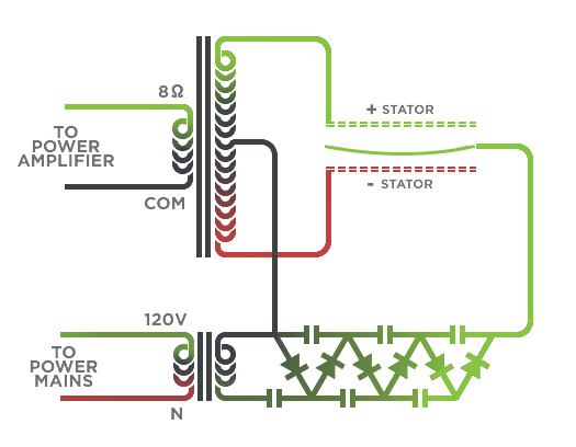
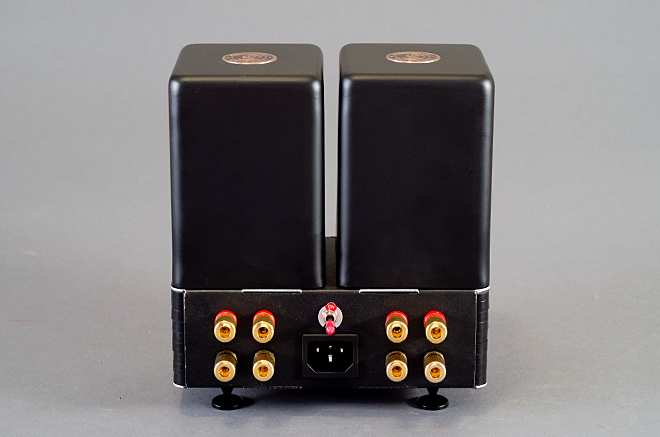
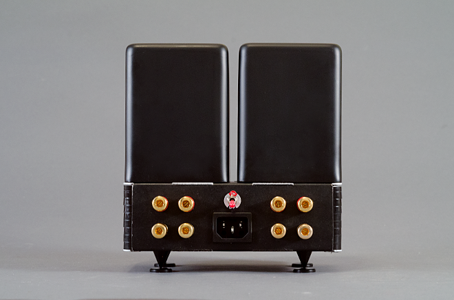
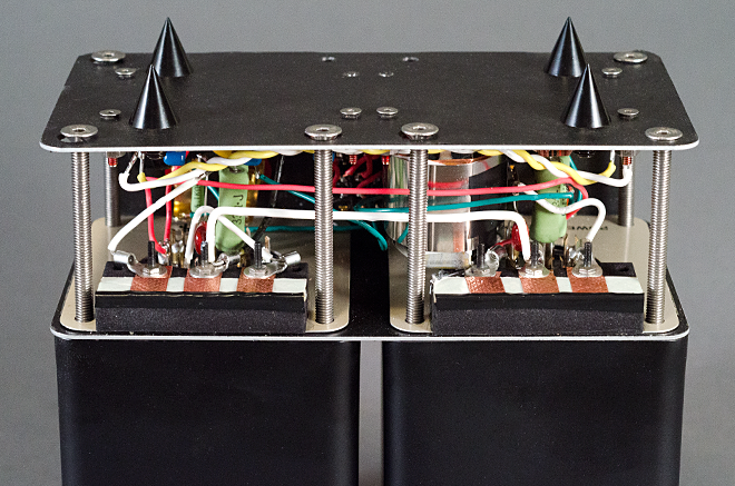
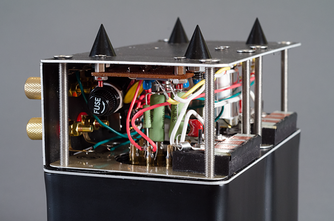
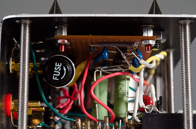
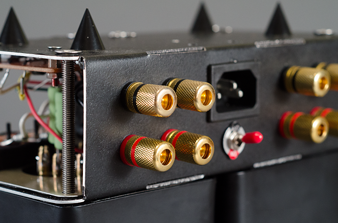
Such a transducer will need a rather unique amplifier to control the two signal stators and biased diaphragm. This is where part one of this project resides; the energizer amplifier. This device is a two channel amplifier that feeds off of any existing audio power amplifier that typically feeds 8 ohm speakers. This amplifier will take high current output from any power amplifier and converts it to low current high voltage outputs making articulation of the electrostatic transducer possible. This approach is a low component low cost solution to energizing electrostatics. The principle theory is taking a classic 5k ohm to 8 ohm audio output transformer and wiring it backwards to produce low current high voltage outputs. Bias the diaphragm with a basic Cockcroft–Walton voltage multiplier and its now ready for signals.
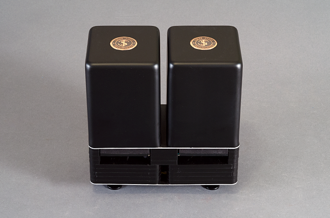
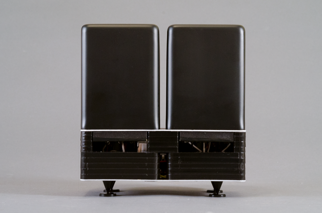
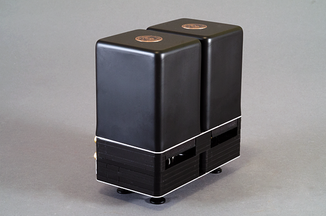
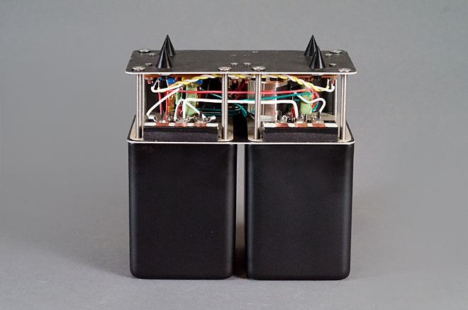
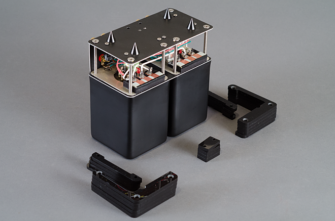
For this project, I wanted to exercise premium components in a compact format. I sourced the transformers from James Audio for their cost effective premium potted Orientcore Hi-B laminations and sourced Silicone coated carbon resistors from Kiwame Japan for their neutral tone.
Using the classic point to point style construction, special sequence of assembly is required to assure a compact functioning form. Using laser cut and bent sheet aluminum and acrylic plates allows for quick and cost effective assembly with little to no machining required. This energizer amplifier has a selector switch to bypass the electrostatic function and go straight to the speakers to avoid any hook up hassle when switching between A & B devices.
Part two will be revealed next.