


This is the second installment of my explorations in higher fidelity audio transducers.
Looking for faster and more accurate audio transducer methods than the standardized voice-coil diaphragm, I became interested in experimenting with the Ultra Low Mass Electrostatic Loudspeaker transducer concepts. The voice-coil diaphragm has been and currently is the most robust cost effective method to sound reproduction while the Electrostatic transducer counterpart has been hailed as the ultimate lowest distortion solution but has been plagued by its more expensive and difficult to manufacture approach. There are other transducer methods out there but the Electrostatic system is the ultimate beast to tame in the audio industry.
The classic voice-coil diaphragm works by transmitting the alternating audio signal through a tightly wound coil that is adhered to a lightweight composite formed cone that is suspended in a magnetic field produced by heavy permanent magnets. The inductance from the signal in the coil suspended through the magnetic flux articulates the cone composite form to convert electrical analog signals into mechanical articulation of air pressure causing what we know of as “sound waves”.
The downside of the voice-coil approach is that the total mass of the copper coils, adhesives, cone, and the flexible elastic surround acts as a spring that has mass greater than the air itself it is trying to move. This means mechanical dampening, ohmic heating, and resonance that means distortion to the original signal. Depending on the given frequency and amplitude of the signal, mechanical and electrical inductance means phase changes that distort and destroy selected frequency ranges (Self resonance). This doesn’t mean that the voice-coil system is unusable, it just means that it will inherently be flawed by distortions imperfections by the nature of its design. No matter how light one can manufacture a voice coil magnet assembly.
The alternative approach is to create a transducer that has the least amount of mass (and mechanical moving parts) physically possible (but with cost in mind, of course). The most appropriate approach is getting an ultra thin film of mylar (thinner than Saran® plastic wrap), and using that as the diaphragm to the transducer. A transducer so low in mass that it would be lighter than the physical air it is trying to move. To have a material this low in mass would virtually eliminate all the phase distortions, resistances and resonances existing from the classic voice-coil approach. A lower distortion solution.
The alternative approach is to create a transducer that has the least amount of mass (and mechanical moving parts) physically possible (but with cost in mind, of course). The most appropriate approach is getting an ultra thin film of mylar (thinner than Saran® plastic wrap), and using that as the diaphragm to the transducer. A transducer so low in mass that it would be lighter than the physical air it is trying to move. To have a material this low in mass would virtually eliminate all the phase distortions, resistances and resonances existing from the classic voice-coil approach. A lower distortion solution.
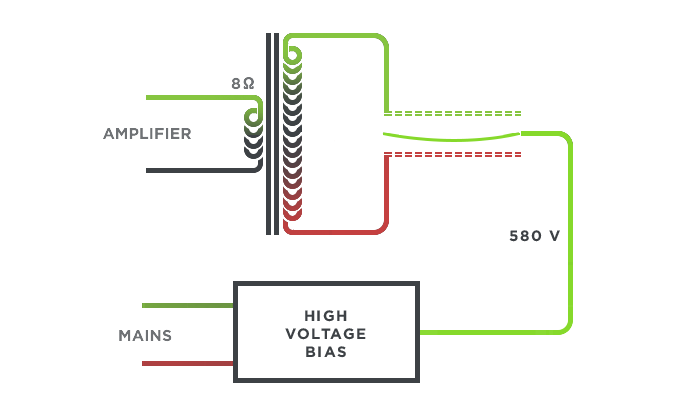
To get such a light weight material to push the heavier air around it in such an articulate way, it must be tensioned tight like a drum and then charged to a high electrostatic voltage potential (like that when rubbing a balloon over your hair). Now that the film has a high bias, it is now capable of being driven by external forces without being physically touched. The higher the voltage bias the more sensitive / articulate it is. I am going to be charging the diaphragm to about a 550V potential.
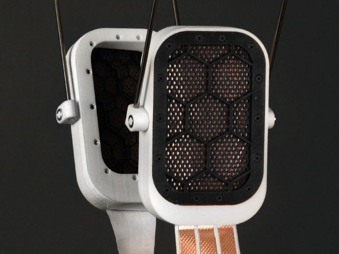
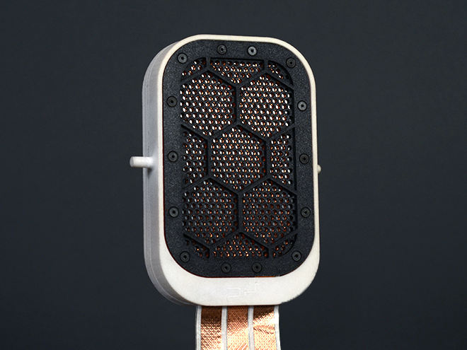
The external force will contain the audio signal to control the film. This external force has to be as close as possible to the film, must be as acoustically transparent as possible and must be as rigid as possible as to not apply its own resonances upon the diaphragm. This plate (or stator) will have plenty of holes in it to allow for maximum acoustic transparency but enough remaining material strength to retain its rigidity to apply its field effect upon the diaphragm without resonating itself. The audio signal will be applied through the stator to effect the diaphragm accordingly. There will be two stators surrounding the diaphragm to assure maximum coverage in a push pull configuration. The audio signal will too need to be boosted to have a high voltage low current output to have proper electrostatic control over the diaphragm.

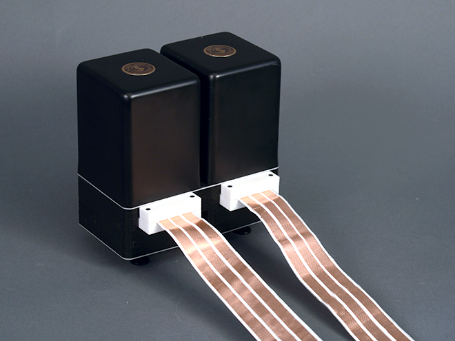
Such a transducer will need a rather unique amplifier to control the two signal stators and biased diaphragm. This is where part one of this project resides; the energizer amplifier. This device is a two channel amplifier that feeds off of any existing audio power amplifier that typically feeds 8 ohm speakers. This amplifier will take high current output from any power amplifier and converts it to low current high voltage outputs making articulation of the electrostatic transducer possible. This approach is a low component low cost solution to energizing electrostatics. The diaphragm is then biased with a Cockcroft–Walton voltage multiplier. This energizer amplifier has a selector switch to bypass the electrostatic function and go straight to the speakers to avoid any hook up hassle when switching between A & B devices.
specific requirements were set early to assure a robust design: (1) Headphone must be comfortable and glasses compatible. (2) Custom parts must be made from affordable and low labor processes. (3) Stators and diaphragm must be exposed to as much open air as possible to avoid internal resonances and acoustic degradation. (4) Body must insulate, protect and hold delicate components at proper tolerance. (5) Assembly must be as quick, and painless as possible. Even on maintenance (6) Must have a large surface area to produce the lowest frequency fall off as possible. (7) Can not touch ears to avoid head aches. (8) Cables must feature low capacitance. (8) Must be harmless to the user. Even when out of operating ranges.
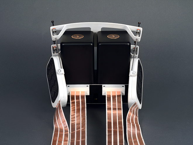
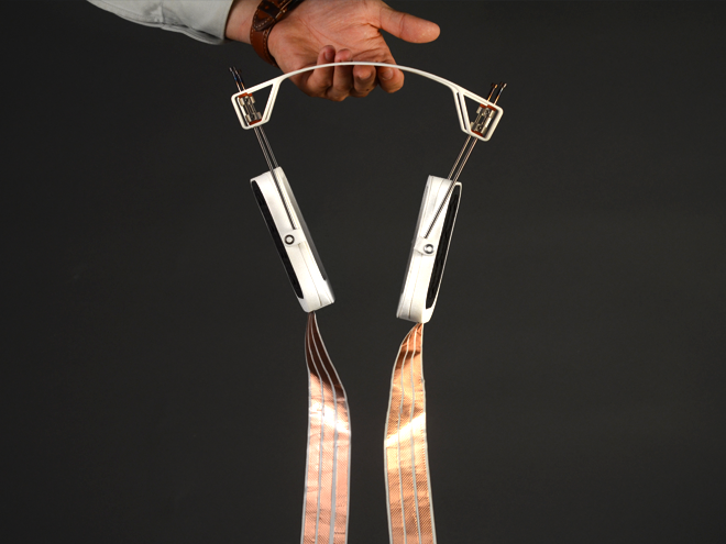
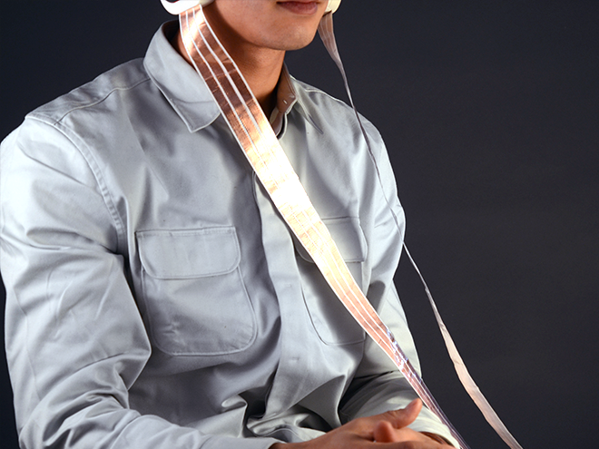
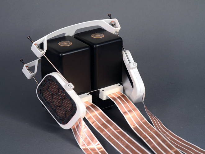
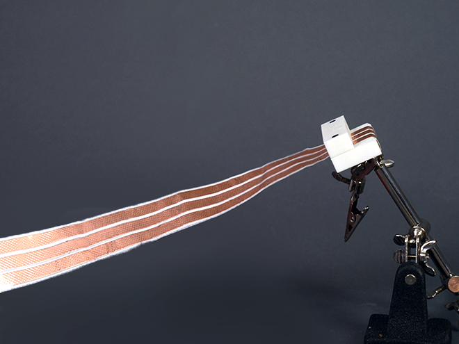
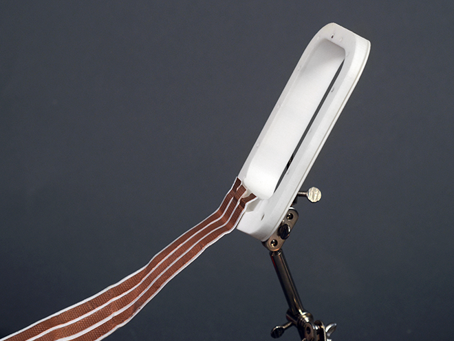
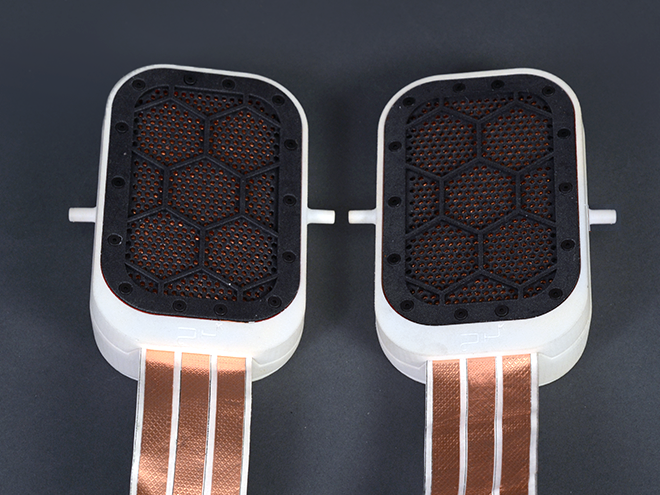
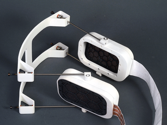
To avoid stray capacitance in the cables to the headphone, conductive ribbon cable was fabricated to make headphone assembly solder free, robust and low on distortion injection.
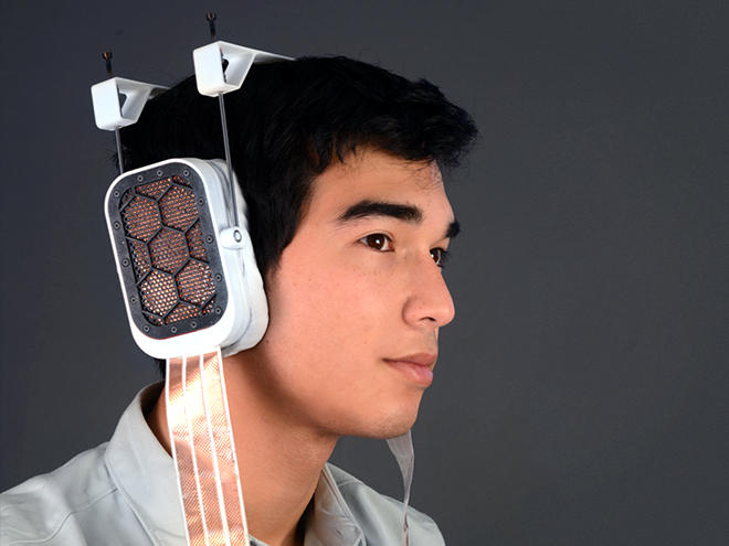
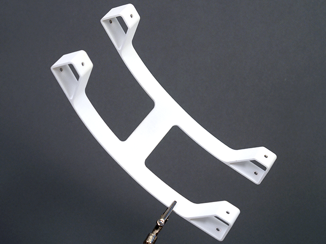
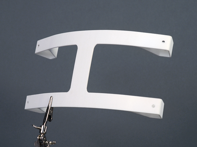
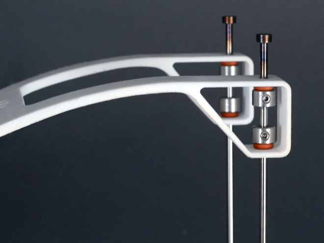
To avoid headaches that are typically found more in classical single headband headphone designs, I chose to make the headband be composed of two simi-independnat flexing forms. This should allow the headphone assembles to twist and wrap more dynamically to peoples heads evenly. An even load is a painless load. The dimensions of the ear speakers are set to be oversize average ear sizes for a complete Circumaural seal. This will help extend the base response by allowing proper sound pressure buildup.

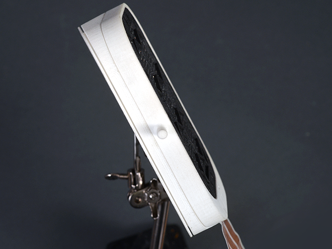
In addition to the even circumaural head seal, the diaphragm plane is angled 15 degrees forward to help simulate a more natural wave path into the ear canal. This should help make the audio feel less “inside the head” sounding. The angled and large diaphragm area will help simulate an enormous soundstage for the ear, allowing for more natural aural acoustics.
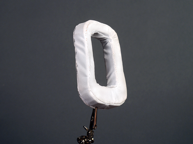
Earpads are sewn with memory foam to assure no point loads on the head. Such as glasses and the vision pains associated with that.
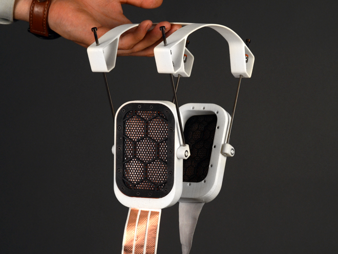
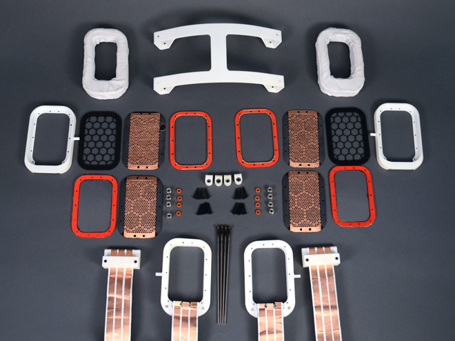
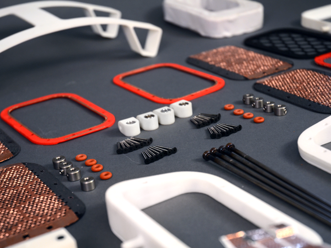
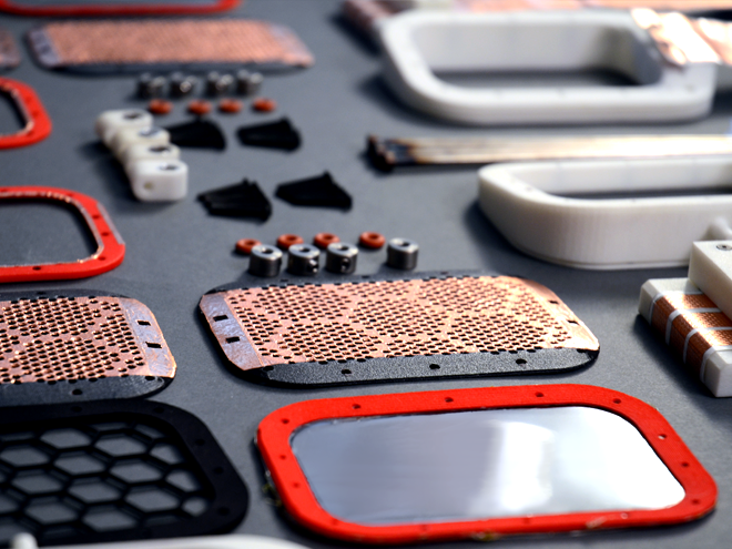
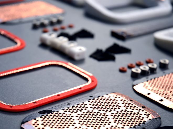
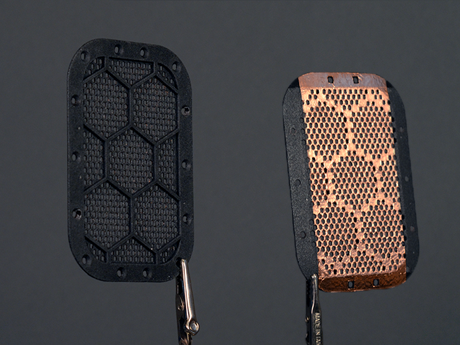
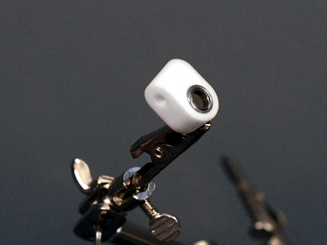
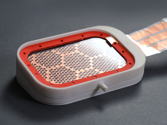
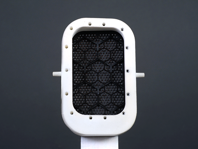
To avoid as much machine shop as possible, Stereolithography Nylon 3D printing was selected for consistent and quick manufacturing. Easily scalable. An additional requirement I ended up putting on myself was to have all custom parts, including the precision gaped stators, spacers and diaphragm holder all be apart of the same Stereolithography process. Because of the limitations on thickness minimums with the Stereolithography printing process, a lot of the internal components were over engineered in a way where it would make printing these thin & high tolerance parts possible. The stator plates had honeycomb structures to assure minimum wall thicknesses and maximum open area be possible with this process. Large layered up honeycomb structures were overlaid onto the stators backs to help rigidify and break up resonance regions with a homogenous perforated surface. Copper was applied to the flattened side to provide the conductive voltage swings necessary to guide the diaphragm. The stators are then sprayed down with a special high insulation spray to help avoid corona discharging and other potentially harmful voltage leakage.
High quality, low inductance, high resistance resistors are placed in line with High voltage lines to assure low minimal current if an accidental arc is ever made anywhere in the product. Capacitance is kept below a humans average capacitance to avoid any unnecessary build up of potential energy.

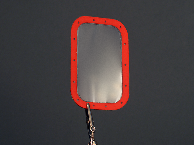
A thin 4um Mylar® diaphragm is stretched homogeneously to 0.5% elongation and is glued to 3D printed angled spacers that allow for more robust spacer parts as well as better centering and locating upon assemblies.
These headphones have not undergone THD analysis or sound pressure level tests yet so the reviews on frequency response are currently subjective. But I can say that these are the clearest, most comfortable pair of headphones I own. Bass response dips around 25 Hz. The high frequencies are crystal sharp and has impressively low listening fatigue. Many straight hours yield a painless experience.
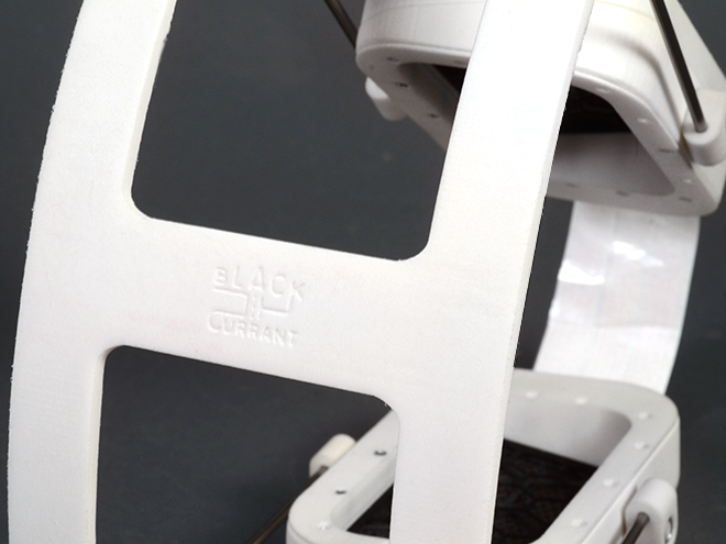
The project and product line has been nicknamed as "Black Currant". Still under research and development, Its estimated release date will be by early 2015 for consumer review and consumption.
Engineered in Rhode Island