


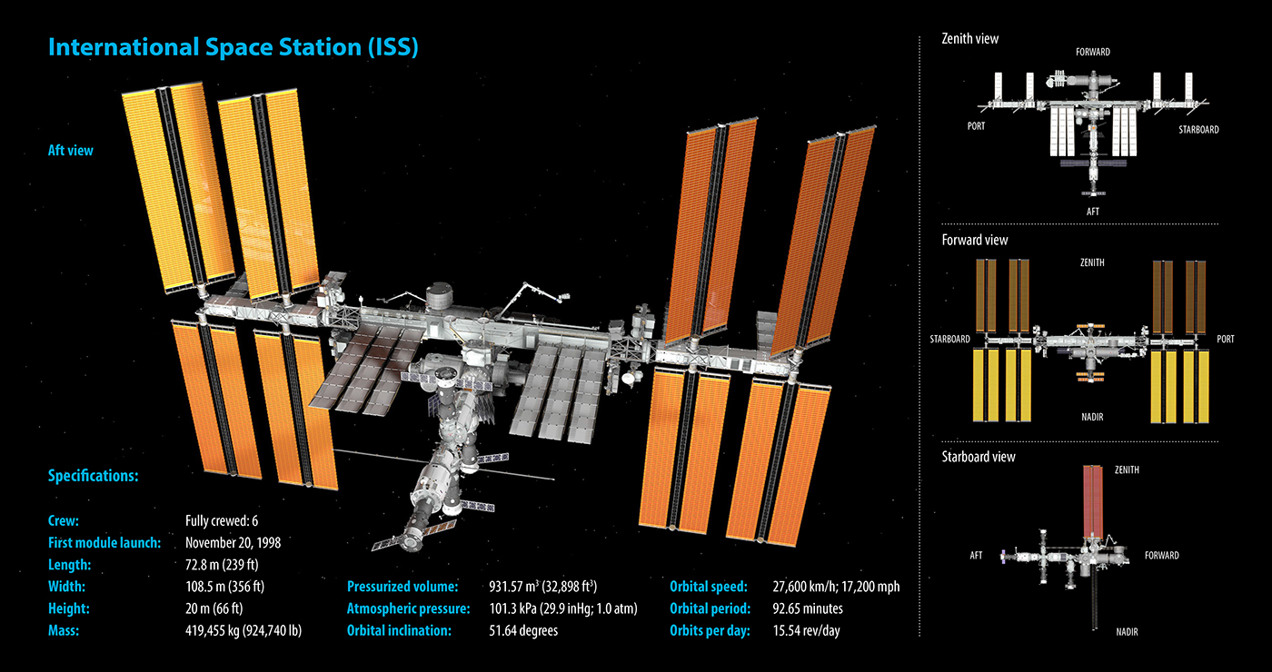

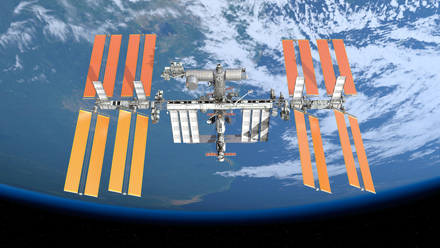
The International Space Station (ISS) is a habitable artificial satellite in low Earth orbit. It is the largest artificial body in orbit and can be seen with naked eye from Earth. The ISS consists of pressurized modules, external trusses, solar arrays, and other components. ISS components have been launched by American Space Shuttle missions, and Russian Proton and Soyuz rockets. First component was launched into orbit in 1998 and the ISS configuration is still being updated with new components, running through at least 2024. The ISS serves as a micro-gravity and space environment research laboratory in which 6 crew members conduct scientific experiments in biology, physics, astronomy, meteorology, and other fields primarily important for further space exploration. The station also conducts tests of spacecraft systems and equipment required for missions to the Moon and Mars. The space station maintains an orbit with an altitude of between 330 and 435 km (205 and 270 mi) by means of reboost manoeuvres using the engines on Russian Service Module "Zvezda" or visiting spacecraft. It completes 15.54 orbits per day.

Time invested in ISS 3D model: 1 year (more than 1100 work hours). Sources: blueprints, diagrams and original ISS photos available openly through Google search. Time invested in Earth 3D model and texture editing: 2 months (more than 200 hours). Visualization rendering: 1 month. Creating Infographics for each module: 2 weeks.

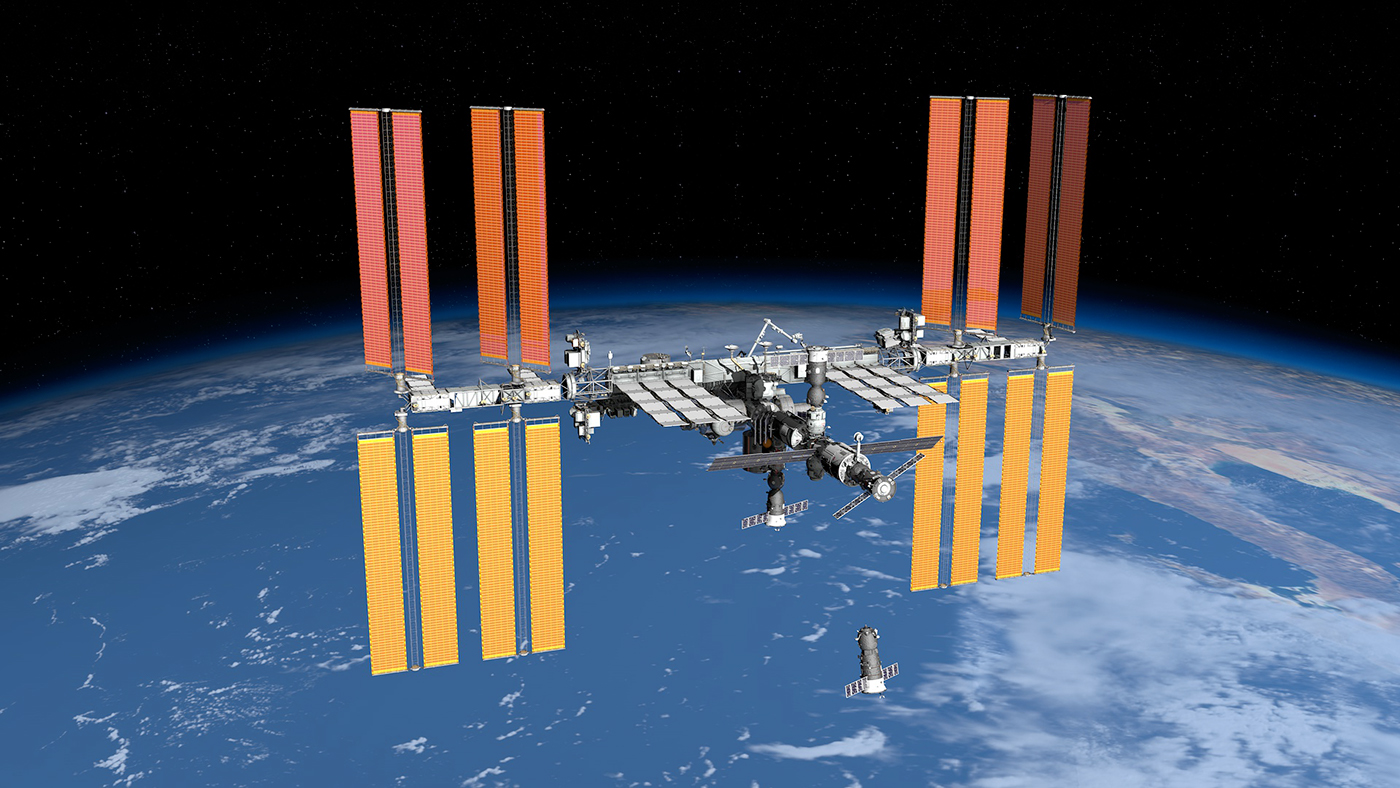
International Space Station over California and Baja California. Russian Expandable Cargo spacecraft "Progress" is approaching with supplies. (3D render)
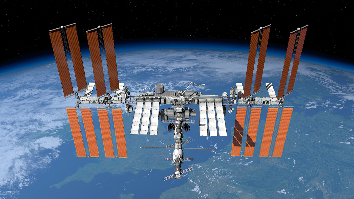
International Space Station over Western Europe - Great Britain and France. (3D render)
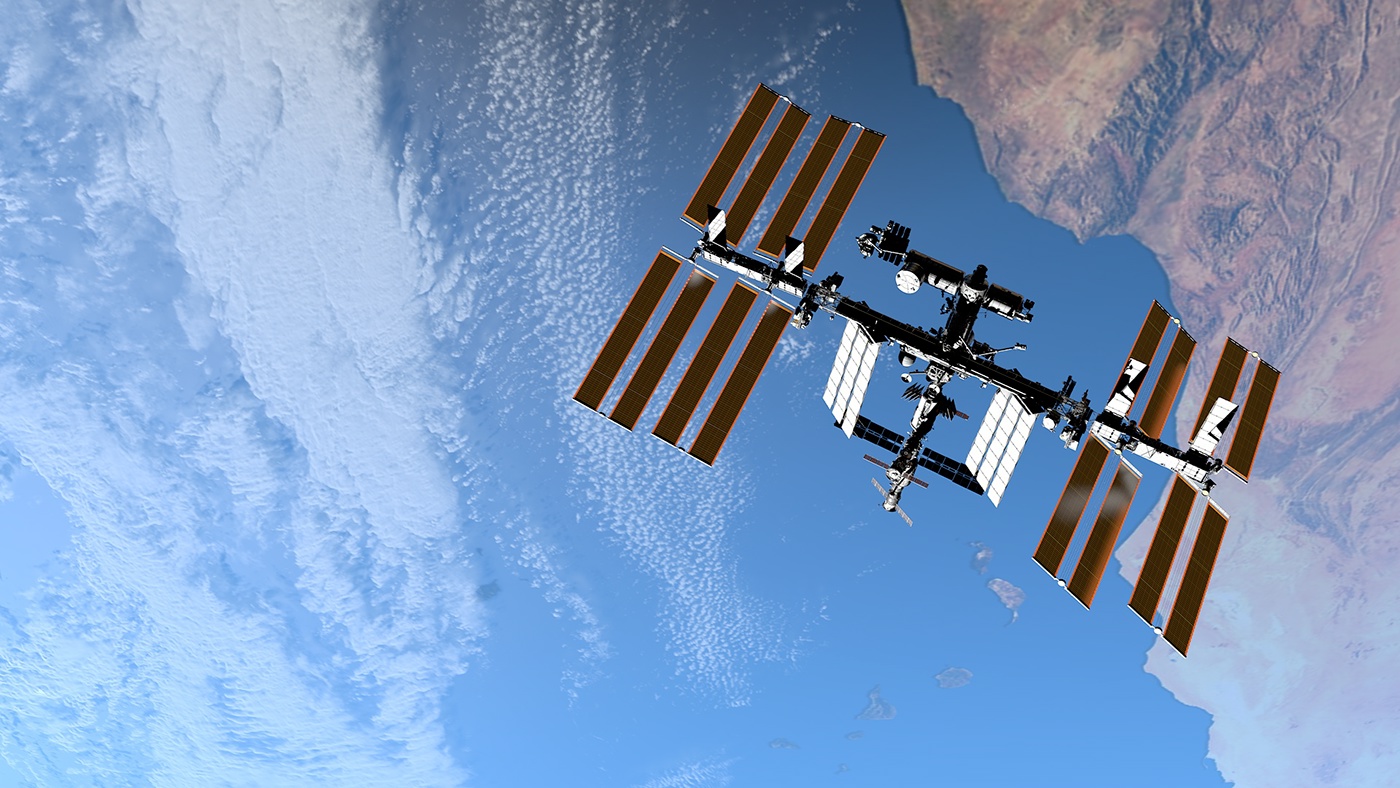
International Space Station over Western Africa. (3D render)

Russian spacecraft "Soyuz" approaching International Space Station with new crew. (3D render)
International Space Station over South America - Brazil. (3D render)
International Space Station over Atlantic Ocean. (3D render)

International Space Station over Mediterranean Sea - Italy and Greece. (3D render)

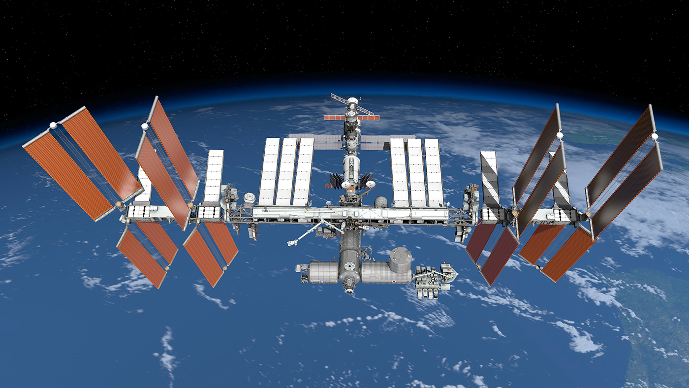
International Space Station seen from beneath. (3D render)


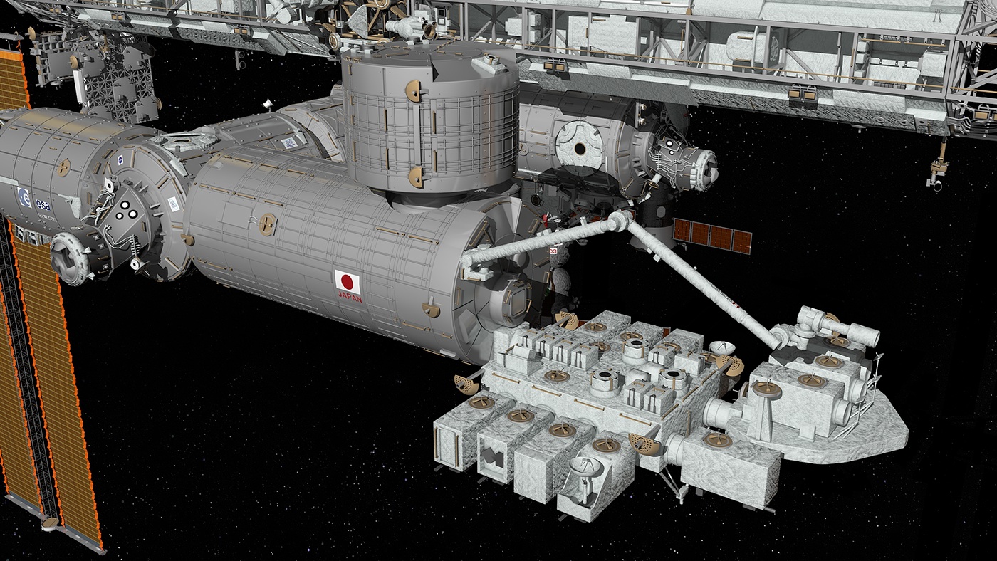
The Kibo module with all components on the ISS configuration. (3D render)
A Japanese science module developed by JAXA, also know as Kibo "Hope". It is the largest single ISS module. Kibō consists of six major elements: 1) Pressurized Module (PM), 2) Exposed Facility (EF), 3) Experiment Logistics Module-Pressurized Section (ELM-PS), 4) Experiment Logistics Module-Exposed Section (ELM-ES), 5) Japanese Experiment Module Remote Manipulator System (JEM-RMS), and 6) Inter-orbit Communication System (ICS).


The Pressurized Module (PM) is the core component connected to the port hatch of the Node 2 Module. It is cylindrical in shape and contains twenty-three International Standard Payload Racks (ISPRs), ten of which are dedicated to science experiments while the remaining 13 are dedicated to Kibo’s systems and storage. The end of the JEM-PM has an airlock and two window hatches. The Exposed Facility, Experiment Logistics Module and the Remote Manipulator System all connect to the pressurized module. Kibo is also the location for many of the press conferences that take place on board the station.

The Remote Manipulator System (JEM-RMS) is a 10 m long robotic arm, mounted at the port cone of the PM, intended to service the EF and to move equipment from and to the ELM. The free end of the arm is able to use the type of grapple fixtures that the Canadarm2 uses.
The Exposed Facility (EF), also known as "Terrace", is located outside the port cone of the PM (which is equipped with an airlock). The EF has 12 EFU (Exposed Facility Unit) ports that attach to PIU (Payload Interface Unit) connectors on EF-EEUs (EF-Equipment Exchange Units). All experiment payloads are fully exposed to the space environment. For proper functioning of these experiments, the payload requires an ORU (Orbital Replacement Unit) which consists of the EPS (Electrical Power System), CT (Communications & Tracking) and the TCS (Thermal Control System).

The Japanese Experiment Logistics Module, Pressurized Section (ELM-PS), also called the JLP, is a pressurized addition to the PM. The module is a storage facility that provides storage space for experiment payloads, samples and spare items. The unpressurized (external) section (ELM-ES) serves the EF as a storage and transportation module.

There are three PMAs located on the International Space Station (ISS). All the PMAs on the ISS are identical but used slightly differently, and all three perform the same basic function of connecting a Common Berthing Mechanism port of an ISS module to an APAS-95 docking port of another module or visiting spacecraft. For this the PMAs carry a passive CBM port and a passive APAS port. They are pressurized and heated from the inside, and through docking rings as well as external connections allow for power and data communications transfer.

PMA-1 was one of the first components of the International Space Station and joins the Russian side of the station with the US side. On STS-88 the crew used the shuttle's robotic arm to attach the Zarya control module to PMA-1, which was already connected to the aft berthing port of Unity. PMA-1 now permanently connects these first two station components.

PMA-2 is currently mounted on the forward port of the Harmony connecting node and was used when Space Shuttle orbiters docked at the station. It is the only PMA that has been outfitted with Station-to-Shuttle Power Transfer System (SSPTS) hardware, which allowed shuttles to stay docked longer to the space station.

After activation of Tranquility, PMA-3 was moved on February 16, 2010 to the port location on Tranquility where the Cupola had been docked for launch.


The Harmony (Node 2) module placed between JEM and Columbus module. (3D render)

Harmony, also known as Node 2, is the "utility hub" of the International Space Station. The hub contains four racks that provide electrical power, plus electronic data, and act as a central connecting point for several other components via its six Common Berthing Mechanisms (CBMs). Harmony added 2,666 cubic feet (75.5 m3) to the station's living volume, an increase of almost 20 percent. The successful installation of Harmony meant that from NASA's perspective, the station was "U.S. Core Complete".


The Bigelow Expandable Activity Module (BEAM) attached to Tranquility module. (3D render)

The Bigelow Expandable Activity Module (BEAM) is an experimental expandable space station module developed by Bigelow Aerospace, under contract to NASA, for testing as a temporary module on the International Space Station (ISS) from 2016 to 2018. Bigelow plans to build a second BEAM module as an airlock for the Bigelow Commercial Space Station.


The Columbus module attached to Harmony module. (3D render)

Columbus is a science laboratory that is part of the International Space Station (ISS) and is the largest single contribution to the ISS made by the European Space Agency (ESA). Like the Harmony and Tranquility modules, the Columbus laboratory was constructed in Turin, Italy by Rome based Thales Alenia Space with respect to structures and thermal control. The functional architecture (including software) of the lab was designed by EADS in Bremen, Germany where it was also integrated before being flown to the Kennedy Space Center (KSC) in Florida in an Airbus Beluga.


The Destiny module connected to the The Integrated Truss Structure. (3D render)

The Destiny module is the primary operating facility for U.S. research payloads aboard the International Space Station (ISS). It was berthed to the Unity module and activated over a period of five days in February, 2001. Destiny is NASA's first permanent operating orbital research station since Skylab was vacated in February 1974. Astronauts work inside the pressurized facility to conduct research in numerous scientific fields. Scientists throughout the world will use the results to enhance their studies in medicine, engineering, biotechnology, physics, materials science, and Earth science.


The Unity module connecting Russian and US/European/Japanese modules. (3D render)


The Unity connecting module was the first U.S.-built component of the International Space Station. It is cylindrical in shape, with six berthing locations (forward, aft, port, starboard, zenith, and nadir) facilitating connections to other modules. Sometimes referred to as Node 1, Unity was the first of the three connecting modules; the other two are Harmony and Tranquility.


The Leonardo Permanent Multipurpose Module (PMM) connected to the Unity module. (3D render)

The Leonardo Permanent Multipurpose Module (PMM) is primarily used for storage of spares, supplies and waste on the ISS, which is currently stored in many different places within the space station. The Leonardo PMM was a Multi-Purpose Logistics Module (MPLM) before 2011, but was modified into its current configuration. It was formerly one of three MPLM used for bringing cargo to and from the ISS with the Space Shuttle. The module was named after Italian polymath Leonardo da Vinci.


The Cupola, PMA 3 and BEAM connected to the Tranquility module. (3D render)


Tranquility, also known as Node 3, is a module of the International Space Station (ISS). ESA and the Italian Space Agency had Tranquility built by Thales Alenia Space. A ceremony on November 20, 2009 transferred ownership of the module to NASA. The module provides six berthing locations, but three of those locations are disabled, as modules originally planned to be attached to Tranquility were canceled. STS-130 brought the Cupola, a large window module and robotics work station to the ISS, which was then attached to the nadir-side of Tranquility. The module also includes various ISS systems, including additional life support systems.

The Cupola is an ESA-built observatory module of the International Space Station (ISS). Its seven windows are used to conduct experiments, dockings and observations of Earth. It was launched aboard Space Shuttle mission STS-130 on 8 February 2010 and attached to the Tranquility (Node 3) module. With the Cupola attached, ISS assembly reached 85 percent completion. The Cupola's 80 cm (31 in) window is the largest ever used in space.


Quest Joint Airlock attached to The Unity module on the ISS. (3D render)

Previously known as the Joint Airlock Module, is the primary airlock for the International Space Station. Quest was designed to host spacewalks with both Extravehicular Mobility Unit (EMU) spacesuits and Orlan space suits. Before Quest was attached, Russian spacewalks using Orlan suits could only be done from the Zvezda service module and American spacewalks using EMUs were only possible when a Space Shuttle was docked.

External stowage platforms (ESPs) are key components of the International Space Station (ISS). Each platform is an external pallet that can hold spare parts, also known as Orbital Replacement Units (ORUs), for the space station. As a platform it is not pressurized, but does require electricity to power the heaters of some of the stored equipment. ORUs are attached to the ESP via Flight Releasable Attachment Mechanisms (FRAMs), matching witness plates that mate the ORU to the platform. The structure of the ESP-2 and ESP-3 platform is based on the deployable version of the Integrated Cargo Carrier (ICC) which was designed to fly inside the Space Shuttle's cargo bay and is owned and operated by Astrium North America, Inc.
The first of the external stowage platforms, called ESP-1, was installed on the port side trunnion pin on the outer hull of the Destiny Laboratory Module on March 13, 2001 during the second EVA of the STS-102 Space Shuttle mission. It is powered by the Unity Module and has two attach points to store ORUs.
ESP-1 was carried into orbit on the underside of an Integrated Cargo Carrier. It is smaller than the other ESPs and ELCs, with dimensions approximately 0.46 m wide by 2.4 m long, and is differently shaped.
ESP-1 holds the following ORUs:
ESP-1 holds the following ORUs:
FRAM-1 Pump flow control system (PFCS) added by the STS-102 crew.; FRAM-2 Direct-current switching unit (DCSU) added by STS-100 crew.

ESP-2 was installed with the assistance of Space Shuttle Discovery's robotic arm and two spacewalkers during the STS-114 mission. It is much larger than ESP-1 with eight FRAM sites creating room for up to eight spare parts (ORUs). Like ESP-1, it is powered by the Unity Module. However, unlike ESP-1, ESP-2 is attached to the Quest Joint Airlock using a specialized ESP Attachment Device (ESPAD). ESP-2 and ESP-3 are deployable versions of the integrated cargo carrier and have the same dimensions, approximately 8.5 feet (2.6 m) long and 14 feet (4.3 m) wide.
The ORUs on ESP-2 are:
The ORUs on ESP-2 are:
FRAM-1 (top side) Failed Pump Module PM-004 relocated here by the ISS-41 US EVA-27 crew in Oct. 2014; FRAM-2 (top side) Direct Current Switching Unit (DCSU) (added by STS-123 crew) FRAM formerly held the VSSA.; FRAM-3 (top side) CTC-3 container moved here via SPDM. DCSU added by STS-123 crew) had been relocated via SPDM Jan. 30, 2013 to ELC-2.; FRAM-4 (top side) Main Bus Switching Unit (MBSU) launched on ESP-2.; FRAM-5 (keel side) Pitch/Roll Joint (P/R-J) added by STS-123 crew. FRAM formerly held a CMG.; FRAM-6 (keel side) Main Bus Switching Unit (MBSU) added by STS-120 crew. This unit was swapped with a failed unit MBSU #1 from the SO truss, by the Exp 32 crew in late 2012.
FRAM-7 (keel side) Flex Hose Rotary Coupler (FHRC SN1003) launched on ESP-2.; FRAM-8 (keel side) Utility Transfer Assembly (UTA) launched on ESP-2.

ESP-3 attached to its location on the lower part of S3 truss segment at the PAS-3 site. (3D render)

ESP-3 was installed on the P3 Truss at UCCAS-1 on August 14, 2007 during the Space Shuttle STS-118 mission. It has seven attachment sites for ISS spare parts and assemblies, called Orbital Replacement Units (ORUs). The platform also has handrails and attachment points for tethers and foot restraints that astronauts can use while working with the ORUs on the ESP-3. ESP-3 was the first major station element to be installed completely by robotics, using only the shuttle and station’s robotic arms, an external berthing camera system (BCS) and a Photovoltaic Radiator Grapple Fixture (PVRGF). On January 12, 2010, the station's robotic arm was used again to move ESP-3 from the P3 truss segment UCCAS-1 site. It was grappled by the arm and then transferred down the station's backbone on the mobile transporter. ESP-3 was then attached to its new location on the lower part of S3 truss segment at the PAS-3 site. Moving the storage platform cleared the way for ExPRESS Logistics Carrier-3 to be installed during STS-134.
The ORUs installed on ESP-3 are:
FRAM-1 (top side) Pitch/roll joint (P/R‐J) launched on ESP-3; FRAM-2 (top side) Flex Hose Rotary Coupler (FHRC SN1004) added by STS-126 crew; FRAM-3 (top side) empty (future home of failed PM SN0004 currently stored on the MBS POA, by the Expedition 38 crew Dec. 2013.; FRAM-4 (top side) Linear Drive Unit (LDU) added by STS-127 crew; FRAM-5 (keel side) Space-to-Ground Antenna (SGANT) added by STS-127 crew; FRAM-6 (keel side) Battery Charge/Discharge Unit (BCDU) launched on ESP-3; FRAM-7 (keel side) ATA Flight Support Equipment (FSE) added by STS-118 crew.

The Integrated Truss Structure (ITS) of the International Space Station (ISS) consists of a linearly arranged sequence of connected trusses on which various unpressurized components are mounted, such as logistics carriers, radiators, solar arrays, and other equipment. It supplies the ISS with a bus architecture. All truss components were named after their planned end-positions: Z for zenith, S for starboard and P for port, with the number indicating the sequential position. The S0 truss might be considered a misnomer, as it is mounted centrally on the zenith position of Destiny and is neither starboard nor port side.

Z1 ITS attached to the Unity Module. (3D render)

The Z1 truss, first truss piece, launched aboard STS-92 in October 2000. It contains the control moment gyroscope (CMG) assemblies, electrical wiring, communications equipment, and two plasma contactors designed to neutralize the static electrical charge of the space station. Another objective of the Z1 truss was to serve as a temporary mounting position for the "P6 truss and solar array" until its relocation to the end of the P5 truss during STS-120. Though not a part of the main truss, the Z1 truss was the first permanent lattice-work structure for the ISS, very much like a girder, setting the stage for the future addition of the station's major trusses or backbones. In October 2007, the P6 was moved to its permanent position next to P5 - the Z1 truss is now solely used to house the CMGs, communications equipment and the plasma contactors; Z1 no longer connects other space station elements to Unity (Node 1).

The S0 truss (also called the Center Integrated Truss Assembly Starboard 0 Truss) forms the center backbone of the Space Station. It was attached on the top of the Destiny Laboratory Module during STS-110 in April 2002. S0 is used to route power to the pressurized station modules and conduct heat away from the modules to the S1 and P1 Trusses. The S0 truss is not docked to the ISS, but is connected with four Module to Truss Structure (MTS) struts.


The P1 and S1 trusses (also called the Port and Starboard Side Thermal Radiator Trusses) are attached to the S0 truss, and contain carts to transport the Canadarm2 and astronauts to worksites along the space station. They each flow 290 kg (637 lb) of anhydrous ammonia through three heat rejection radiators. The S1 truss was launched on STS-112 in October 2002 and the P1 truss was launched on STS-113 in November 2002. Detailed design, test and construction of the S1 and P1 structures was conducted by McDonnell Douglas (now Boeing) in Huntington Beach, CA. First parts were cut for the structure in 1996, and delivery of the first truss occurred in 1999.


The P3/P4 truss assembly was installed by the Space Shuttle Atlantis STS-115 mission, launched September 9, 2006, and attached to the P1 segment. The P3 and P4 segments together contain a pair of solar arrays, a radiator and a rotary joint that will aim the solar arrays, and connects P3 to P4. Upon its installation, no power was flowing across the rotary joint, so the electricity generated by the P4 solar array wings was only being used on the P4 segment, and not the rest of the station. Then in December 2006 a major electrical rewiring of the station by STS-116 routed this power to the entire grid. The S3/S4 truss assembly—a mirror-image of P3/P4—was installed on June 11, 2007 also by Space Shuttle Atlantis during flight STS-117, mission 13A and mounted to the S1 truss segment.
Major P3 and S3 subsystems include the Segment-to-Segment Attach System (SSAS), Solar Alpha Rotary Joint (SARJ), and Unpressurized Cargo Carrier Attach System (UCCAS). The primary functions of the P3 truss segment are to provide mechanical, power and data interfaces to payloads attached to the two UCCAS platforms; axial indexing for solar tracking, or rotating of the arrays to follow the sun, via the SARJ; movement and work site accommodations for the Mobile Transporter. The P3/S3 primary structure is made of a hexagonal shaped aluminum structure and includes four bulkheads and six longerons. The S3 truss also supports EXPRESS Logistics Carrier locations, first to be launched and installed in the 2009 time frame.
Major subsystems of the P4 and S4 Photovoltaic Modules (PVM) include the two Solar Array Wings (SAW), the Photovoltaic Radiator (PVR), the Alpha Joint Interface Structure (AJIS), and Modified Rocketdyne Truss Attachment System (MRTAS), and Beta Gimbal Assembly (BGA).


The P5 and S5 trusses are connectors which support the P6 and S6 trusses, respectively. The P3/P4 and S3/S4 truss assemblies' length was limited by the cargo bay capacity of the Space Shuttle, so these small connectors are needed to extend the truss. The P5 truss was installed on December 12, 2006 during the first EVA of mission STS-116. The S5 truss was brought into orbit by mission STS-118 and installed on August 11, 2007.


The P6 truss was the second truss segment to be added, because it contains a large Solar Array Wing (SAW) that generated essential electricity for the station, prior to activation of the SAW on the P4 truss. It was originally mounted to the Z1 truss and had its SAW extended during STS-97, but the SAW was folded, one half at a time, to make room for the SAWs on the P4 and S4 trusses, during STS-116 and STS-117 respectively. Shuttle mission STS-120 (assembly mission 10A) detached the P6 truss from Z1, remounted it on the P5 truss, redeployed its radiator panels and attempted to redeploy its SAWs. One SAW (2B) was deployed successfully but the second SAW (4B) developed a significant tear that temporarily stopped deployment at around 80%. This was subsequently fixed and the array is now fully deployed. A later assembly mission (the out of sequence STS-119) mounted the S6 truss on the S5 truss, which provided a fourth and final set of solar arrays and radiators.


The International Space Station's main source of energy is from three of the four large U.S.-made photovoltaic arrays currently on the station, sometimes referred to as the Solar Array Wings (SAW). Each of the Solar Array Wings are 34 m (112 ft) long by 12 m (39 ft) wide, and are capable of generating nearly 32.8 kW of DC power.[9] They are split into two photovoltaic blankets, with the deployment mast in between. Each blanket has 16,400 silicon photovoltaic cells, each cell measuring 8 cm x 8 cm, grouped into 82 active panels, each consisting of 200 cells, with 4,100 diodes.

The sequential shunt unit (SSU) is designed to coarsely regulate the solar power collected during periods of insolation—when the arrays collect power during sun-pointing periods. A sequence of 82 separate strings, or power lines, leads from the solar array to the SSU. Shunting, or controlling, the output of each string regulates the amount of power transferred. The regulated voltage setpoint is controlled by a computer located on the IEA and is normally set to around 140 volts. The SSU has an overvoltage protection feature to maintain the output voltage below 200 V DC maximum for all operating conditions. This power is then passed through the BMRRM to the DCSU located in the IEA.

An ExPRESS logistics carrier (ELC) is an unpressurized attached payload platform for the International Space Station (ISS) that provides mechanical mounting surfaces, electrical power, and command and data handling services for Orbital Replacement Units (ORUs) as well as science experiments on the ISS. ("ExPRESS" stands for Expedite the Processing of Experiments to the Space Station.) An ELC provides scientists with a platform and infrastructure to deploy experiments in the vacuum of space without requiring a separate dedicated Earth-orbiting satellite.
ELCs interface directly with the ISS integrated truss common attach system (CAS). The P3 Truss has two such attach points called Unpressurised Cargo Carrier Attachment System (UCCAS) mechanisms, one facing zenith (space facing) called UCCAS-1, the other facing nadir (earth facing) called UCCAS-2. Whereas the S3 Truss has four similar locations called Payload Attachment System (PAS) mechanisms, two facing Zenith (PAS-1 and PAS-2), and two facing Nadir (PAS-3 and PAS-4).

ELC-1 is located on the P3 truss at the UCCAS-2 (nadir, earth facing) site. (3D render)

ELC-1 is located on the P3 truss at the UCCAS-2 (nadir, earth facing) site. ELC-1 weighs approximately 13,840 lbs. Carries 9 FRAMS.
FRAM (Flight Releasable Attachment Mechanism) on ELC-1: FRAM-1 (top side) Latching End Effector (LEE) launched on ELC-1; FRAM-2 (top side) Plasma Contactor Unit (PCU) launched on ELC-1; FRAM-3 (top side) STP-H4 (delivered by the HTV-4 Exposed Pallet, was placed here by the SSRMS/SPDM Aug. 2013); FRAM-4 (top side) Battery Charger Discharge Unit (BCDU) launched on ELC-1; FRAM-5 (top side) Control Moment Gyroscope (CMG SN104) launched on ELC-1; FRAM-6 (keel side) Nitrogen Tank Assembly (NTA SN0002) launched on ELC-1; FRAM-7 (keel side) Pump Module (PM SN0007) launched on ELC-1; FRAM-8 (keel side) OPALS Payload (placed via Dextre/SSRMS May 7, 2014. Delivered by SpaceX Dragon CRS-3); FRAM-9 (keel side) Ammonia Tank Assembly (ATA) launched on ELC-1
FRAM (Flight Releasable Attachment Mechanism) on ELC-1: FRAM-1 (top side) Latching End Effector (LEE) launched on ELC-1; FRAM-2 (top side) Plasma Contactor Unit (PCU) launched on ELC-1; FRAM-3 (top side) STP-H4 (delivered by the HTV-4 Exposed Pallet, was placed here by the SSRMS/SPDM Aug. 2013); FRAM-4 (top side) Battery Charger Discharge Unit (BCDU) launched on ELC-1; FRAM-5 (top side) Control Moment Gyroscope (CMG SN104) launched on ELC-1; FRAM-6 (keel side) Nitrogen Tank Assembly (NTA SN0002) launched on ELC-1; FRAM-7 (keel side) Pump Module (PM SN0007) launched on ELC-1; FRAM-8 (keel side) OPALS Payload (placed via Dextre/SSRMS May 7, 2014. Delivered by SpaceX Dragon CRS-3); FRAM-9 (keel side) Ammonia Tank Assembly (ATA) launched on ELC-1

ELC-2 is located on the S3 truss at the PAS-1 (zenith, space facing) site, alongside AMS-2 at PAS-2. (3D render)

ELC-2 is located on the S3 truss at the PAS-1 (zenith, space facing) site, alongside AMS-2 at PAS-2. ELC-2 weighs approximately 13,400 lbs. Carries 9 FRAMs.
FRAM-1 (top side) DCSU placed here by SPDM from ESP-2 on Jan. 30, 2013. (CTC-3 moved to FRAM-2 for a test of the SPDM December 22/23, 2011); FRAM-2 (top side) Cargo Transport Container-3 (CTC-3) launched on ELC-2 (moved from FRAM-1 – see above); FRAM-3 (top side) MISSE base - MISSE-8 was removed by the Exp. 36 crew Jul. 2013 (STS-134 added MISSE-8 replacing MISSE-7 which was launched on ELC-2. STS-135 added MISSE-8 'ORMatE-III exposure plate' to the second MISSE mount); FRAM-4 (top side) High Pressure Gas Tank (HPGT) (Oxygen depleted) replaced the one carried up on ELC-2, which was used to replace a depleted tank from Quest in EVA during STS-129; FRAM-5 (top side) Control Moment Gyroscope (CMG SN102) launched on ELC-2; FRAM-6 (keel side) Pump Module (PM SN0005) launched on ELC-2; FRAM-7 (keel side) MBSU (delivered by the HTV-4 Exposed Pallet, and placed here by the SSRMS/SPDM Aug. 2013); FRAM-8 (keel side) Mobile Transporter Trailing Umbilical System-Reel Assembly (MT TUS-RA) launched on ELC-2; FRAM-9 (keel side) Nitrogen Tank Assembly (NTA SN0003) launched on ELC-2

ELC-3 is located on the P3 truss at the UCCAS-1 (zenith, space facing) site. (3D render)

ELC-3 is located on the P3 truss at the UCCAS-1 (zenith, space facing) site. ELC-3 weighs 14,023 lbs.
FRAM-1 (top side) Cargo Transport Container-5 (CTC-5) launched on ELC-3; FRAM-2 (top side) Special Purpose Dextrous Manipulator (SPDM) Arm launched on ELC-3; FRAM-3 (top side) SCAN Testbed (arrived in July 2012 via HTV-3); FRAM-4 (top side) S band Antenna Sub-System Assembly #3 (SASA) launched on ELC-3; FRAM-5 (keel side) Space Test Program-Houston 3 (STP-H3) DOD experiment launched on ELC-3 (removed by the SPDM and placed on HTV-4 for disposal); FRAM-6 (keel side) Ammonia Tank Assembly (ATA) launched on ELC-3; FRAM-7 (keel side) High Pressure Gas Tank (HPGT) launched on ELC-3; FRAM-8 (keel side) S band Antenna Sub-System Assembly #2 (SASA) launched on ELC-3

ELC-4 is located on the S3 truss at the PAS-4 (nadir, earth facing) site, alongside ESP-3 at PAS-3. ELC-4 weighs 8,235 lbs. Heat Rejection System Radiator (HRSR) was launched on the top side of ELC-4.
FRAM-1 (keel side) Cargo Transport Container-2 (CTC-2) delivered to ISS by HTV-2 (EP) via SPDM held by the SPDM since its initial delivery by the HTV-2; FRAM-2 (keel side) empty; FRAM-3 (keel side) Robotic Refuelling Mission (RRM) was delivered to the ISS by STS-135, placing it temporarily on the SPDM at Destiny. The RRM held by the SPDM was later moved to this FRAM; FRAM-4 (keel side) Utility Transfer Assembly (delivered by HTV-4 EP via SPDM Aug. 2013); FRAM-5 (keel side) Flex Hose Rotary Coupler (FHRC SN1005) delivered to the ISS by HTV-2 Exposed Pallet (EP), was then moved to this FRAM via SPDM
FRAM-1 (keel side) Cargo Transport Container-2 (CTC-2) delivered to ISS by HTV-2 (EP) via SPDM held by the SPDM since its initial delivery by the HTV-2; FRAM-2 (keel side) empty; FRAM-3 (keel side) Robotic Refuelling Mission (RRM) was delivered to the ISS by STS-135, placing it temporarily on the SPDM at Destiny. The RRM held by the SPDM was later moved to this FRAM; FRAM-4 (keel side) Utility Transfer Assembly (delivered by HTV-4 EP via SPDM Aug. 2013); FRAM-5 (keel side) Flex Hose Rotary Coupler (FHRC SN1005) delivered to the ISS by HTV-2 Exposed Pallet (EP), was then moved to this FRAM via SPDM


Robotic system on board the International Space Station (ISS) plays a key role in station assembly and maintenance. (3D render)

The Mobile Servicing System (MSS), is a robotic system on board the International Space Station (ISS). Launched to the ISS in 2001, it plays a key role in station assembly and maintenance; it moves equipment and supplies around the station, supports astronauts working in space, and services instruments and other payloads attached to the ISS and is used for external maintenance. Astronauts receive specialized training to enable them to perform these functions with the various systems of the MSS.
The MSS is composed of three components - the Space Station Remote Manipulator System (SSRMS), known as Canadarm2, the Mobile Remote Servicer Base System (MBS) and the Special Purpose Dexterous Manipulator (SPDM, also known as Dextre or Canada hand). The system can move along rails on the Integrated Truss Structure on top of the US provided Mobile Transporter cart which hosts the MRS Base System.
The MSS was designed and manufactured by MDA Space Missions (previously called MD Robotics; previously called SPAR Aerospace) for the Canadian Space Agency's contribution to the International Space Station.
The Mobile Remote Servicer Base System (MBS) is a base platform for the robotic arms. It was added to the station during STS-111 in June 2002. The platform rests atop the Mobile Transporter (installed on STS-110, designed by Northrop Grumman in Carpinteria, CA), which allows it to glide 108 metres down rails on the station's main truss.
The Mobile Remote Servicer Base System (MBS) is a base platform for the robotic arms. It was added to the station during STS-111 in June 2002. The platform rests atop the Mobile Transporter (installed on STS-110, designed by Northrop Grumman in Carpinteria, CA), which allows it to glide 108 metres down rails on the station's main truss.

The Special Purpose Dexterous Manipulator, or "Dextre", is a smaller two-armed robot that can attach to Canadarm2, the ISS or the Mobile Base System. The arms and its power tools are capable of handling the delicate assembly tasks and changing Orbital Replacement Units (ORUs) currently handled by astronauts during space walks. Although Canadarm2 can move around the station in an "inchworm motion", it's unable to carry anything with it unless Dextre is attached. Testing was done in the space simulation chambers of the Canadian Space Agency's David Florida Laboratory in Ottawa.

The Orbiter Boom Sensor System (OBSS) was a 50-foot boom carried on board NASA's Space Shuttles. The boom was grappled by the Canadarm and served as an extension of the arm, doubling its length to a combined total of 100 feet (30 m). At the far end of the boom was an instrumentation package of cameras and lasers used to inspect the shuttle for damage to the heat shield, officially called the Thermal Protection System (TPS), that could jeopardize the shuttle during re-entry. The decision to perform focused inspections of the TPS was prompted by the Space Shuttle Columbia disaster, in which Columbia was destroyed due to damage inflicted to its TPS during lift-off.


Particle physics experiment module that is mounted on the International Space Station. (3D render)

The Alpha Magnetic Spectrometer (AMS-02) is a particle physics experiment module that is mounted on the International Space Station (ISS). It is designed to measure antimatter in cosmic rays and search for evidence of dark matter. This information is needed to understand the formation of the Universe. The principal investigator is Nobel laureate particle physicist Samuel Ting. By April 15, 2015, AMS-02 had recorded over 60 billion cosmic ray events since its installation.


Functional Cargo Block Zarya attached to the Unity module. (3D render)


Aft view of Zarya module. (3D render)
Also known as the Functional Cargo Block or FGB on Russian, was the first module of the International Space Station to be launched. The FGB provided electrical power, storage, propulsion, and guidance to the ISS during the initial stage of assembly. With the launch and assembly in orbit of other modules with more specialized functionality, Zarya is now primarily used for storage, both inside the pressurized section and in the externally mounted fuel tanks. The Zarya is a descendant of the TKS spacecraft designed for the Russian Salyut program. The name Zarya, which means sunrise, was given to the FGB because it signified the dawn of a new era of international cooperation in space.


Rassvet attached to the Nadir position of Zarya module. (3D render)

Rassvet also known as the Mini-Research Module 1 (MRM-1) and formerly known as the Docking Cargo Module (DCM), is a component of the International Space Station (ISS). The module's design is similar to the Mir Docking Module launched on STS-74 in 1995. Rassvet is primarily used for cargo storage and as a docking port for visiting spacecraft.


Pirs attached to Nadir hatch of the Zvezda module. (3D render)

Also called "Stykovochny Otsek 1" or "SO-1" is one of the two Russian docking compartments originally planned for the ISS. Pirs was launched in August 2001. It provides the ISS with one docking port for Soyuz and Progress spacecraft, and allows egress and ingress for spacewalks by cosmonauts using Russian Orlan space suits. A second docking compartment, "Stykovochniy Otsek 2" or SO-2, was initially planned with the same design. However, when the Russian segment of the ISS was redesigned in 2001, the new design no longer included the SO-2, and its construction was canceled. After another change of plans the SO-2 module finally evolved into the Poisk module, which was added to the ISS in 2009.


Also known as the Mini-Research Module 2 (MRM 2) is a docking module of the International Space Station. It's original name was Docking Module 2 (Stykovochniy Otsek 2 (SO-2)), as it is almost identical to the Pirs Docking Compartment. Added in 2009, Poisk was the first major Russian addition to the International Space Station since 2001.


Zenith view of Zvezda module. (3D render)

Aft view of Zvezda module. (3D render)
Zvezda, also known as the Zvezda Service Module, is a component of the International Space Station (ISS). It was the third module launched to the station, and provides all of the station's life support systems, some of which are supplemented in the USOS, as well as living quarters for two crew members. It is the structural and functional center of the Russian portion of the station - the Russian Orbital Segment. The basic structural frame of Zvezda, known as "DOS-8", was initially built in the mid-1980s to be the core of the Mir-2 space station. This means that Zvezda is similar in layout to the core module (DOS-7) of the Mir space station. The space frame was completed in February 1985 and major internal equipment was installed by October 1986.


Progress MS and Soyuz MS docked to the ISS. (3D render)

The Progress is a Russian expendable cargo spacecraft. Its purpose is to deliver supplies needed to sustain human presence in orbit. While it does not carry a crew it can be boarded by astronauts when docked with a space station, hence it being classified as manned by its manufacturer. Progress is derived from the manned Soyuz spacecraft and launches on the same vehicle, a Soyuz rocket.
Progress has supported space stations as early as Salyut 6 and as recently as the International space station. Each year there are between three and four Progress flights to the ISS. A Progress remains docked until shortly before being replaced with a new one or a Soyuz (which will use the same docking port). Then it is filled with waste, disconnected, and de-orbited, at which point it burns up in the atmosphere. Due to the variation in Progress vehicles flown to the ISS, NASA uses its own nomenclature where "ISS 1P" means the first Progress spacecraft to ISS. As of April 28, 2015 there have been 140 flights with three failures.

Soyuz (Russian: Union) is a series of spacecraft designed for the Soviet space programme by the Korolyov Design Bureau (now RKK Energia) in the 1960s that remains in service today. The Soyuz succeeded the Voskhod spacecraft and was originally built as part of the Soviet Manned Lunar programme. The Soyuz spacecraft is launched on a Soyuz rocket, the most frequently used and most reliable launch vehicle in the world to date. The Soyuz rocket design is based on the Vostok launcher, which in turn was based on the 8K74 or, a Soviet intercontinental ballistic missile.


